I recently had to replace the ESP32 chip in my OSR2+ and I’m having trouble figuring out the pins any advice?
Check the source code; these are the defaults ![]()
// Pin assignments
// T-wist feedback goes on digital pin 2
#define LowerLeftServo_PIN 15    // Lower Left Servo (OSR2 Left Servo)
#define UpperLeftServo_PIN 2     // Upper Left Servo
#define LowerRightServo_PIN 13   // Lower Right Servo (OSR2 Right Servo)
#define UpperRightServo_PIN 12   // Upper Right Servo
#define LeftPitchServo_PIN 4     // Left Pitch Servo (OSR2 Pitch Servo)
#define RightPitchServo_PIN 14   // Right Pitch Servo
#define TwistServo_PIN 27        // Twist Servo
#define ValveServo_PIN 25        // Valve Servo
#define TwistFeedback_PIN 26     // Twist Servo Feedback
#define Vibe0_PIN 18             // Vibration motor 1
#define Vibe1_PIN 19             // Vibration motor 2
If you’re feeling adventurous you can wifi enable your ESP32 by installing a different firmware. Then you can remap your pins from a webclient:
https://www.patreon.com/posts/tcode-esp32-v0-72911666
Thanks for the diagram IMG helps a lot. To make sure when I flash using the ESP32 I want to use SR6-Alpha4_esp32 correct?
Yes, you need to use the SR6 firmware and set it to OSR2 mode. Just follow the instructions and you’ll be grand ![]()
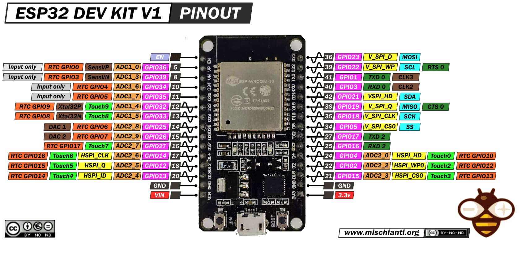
Okay thank, one more the diagram the numbers in brown/black box are the pins i need to connect right or do i go off the d-numbers ? I only ask because for the pitch servo it says pin 4 and i don’t see a 4 .
Again thank you so much for the help!
Match the pins to the numbers shown in Pink in the diagram in my first post (GPIO xx, etc). The labels on the board near the pins should also display the pin number. Hope this helps.

2 Likes